
Workflow · 8 min read
How to engrave serial numbers into a batch of 3D prints
Numbering a production run without CAD: where to put the mark, how deep to cut it, and how to keep the digits readable after the first layer lines appear.
By Alok Kumar · · updated
Once you print the same part more than about twenty times, you need to be able to tell the copies apart. Which ones came off the machine that was drifting. Which batch used the older filament. Which unit the client is complaining about. A serial number cut into the model solves all of it, and it costs nothing per part because it happens before slicing.
The awkward bit is that adding a different number to each of sixty models normally means sixty trips through CAD. It does not have to.
Engrave, don’t emboss
You can either cut the number into the surface or raise it above the surface. For batch numbering, cut it in, every time.
- Raised text needs support and catches on things. On a vertical face it overhangs; on a top face it prints fine but snaps off in a bag of parts.
- Recessed text is protected. It survives tumbling, sanding and years of handling, because the surface around it takes the wear instead.
- Recessed text is easier to read. Shadow inside the cut gives contrast even in a single colour. Raised text on the same colour part is nearly invisible.
Choose the face before you choose the number
The mark should be somewhere a person can find deliberately and never notices otherwise. In practice that means:
- A flat face. Curved surfaces distort the digits and make depth inconsistent across the mark.
- The underside or the back, if the part has a presentation side. Nothing about a serial number is decorative.
- Not a mating surface. A recess on a face that has to sit flat against something else is a leak path, a rock, or a glue failure waiting to happen.
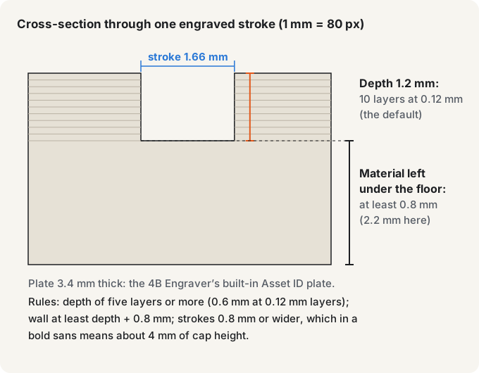
- Not a thin wall. Cutting 1 mm into a 1.2 mm wall leaves 0.2 mm, which will not survive the part being dropped. Keep at least depth + 0.8 mm of wall: 2.0 mm for a 1.2 mm cut. 4B Engraver measures the material under the cut and refuses a depth that breaks this.
If the part is printed face-down on the bed, remember the bottom surface is the smoothest one you will get. It is usually the best place for a mark, and the engraving will come out crisper there than anywhere else.
Depth: 1.2 mm, and never fewer than five layers
Depth is a trade between readability and strength. 4B Engraver offers 0.6, 0.9, 1.2, 1.5 and 2.0 mm, and starts at 1.2 mm. A slicer cuts a recess as a whole number of layers, so count layers rather than millimetres.
| Depth | Layers at 0.12 mm | Layers at 0.2 mm | Result |
|---|---|---|---|
| 0.6 mm | 5 | 3 | The minimum, and only at fine layers. Readable in good light, easy to lose under a coat of paint. For thin walls. |
| 1.2 mm | 10 | 6 | The default. Reliable shadow, survives sanding and paint, costs almost no strength. |
| 2.0 mm | about 17 | 10 | Only for large parts or when the mark must survive heavy finishing. Needs 2.8 mm of wall. |
The rule underneath: at least five layer heights. That is 0.6 mm at a 0.12 mm layer, but 1.0 mm at 0.2 mm layers, so on a coarse profile use the 1.2 mm default. Anything shallower and the slicer may render the recess as a surface texture rather than a cut, which reads as a smudge.
Size the digits for the printer, not the screen
The number looks perfectly clear in a 3D preview at any size. On the machine it is limited by the nozzle. A 0.4 mm nozzle cannot cut a feature narrower than about 0.4 mm, so the gaps inside an 8 or a 6 close up if the digits are too small.
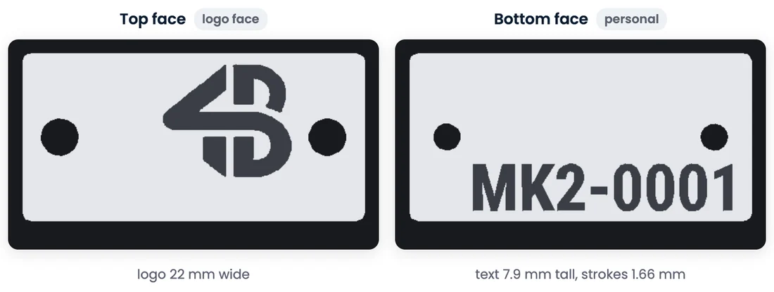
The real limit is stroke width: a recessed stroke narrower than 0.8 mm lets the walls on either side of it merge, and the groove fills in. In a bold sans like the one 4B Engraver uses, the thinnest stroke is about a fifth of the cap height, so 0.8 mm strokes arrive at about 4 mm of cap height. Treat 4 mm as the minimum to design for with a 0.4 mm nozzle.
Below that, the engraver tries to help: it measures the narrowest stroke and thickens the letters by up to 0.22 mm to reach 0.8 mm, and it warns you when strokes stay under 0.8 mm or when text would be under 2.5 mm tall. Treat that 2.5 mm warning as the point where the tool gives up, not as a second target. The measurements behind these figures, from printed parts, are on the engraver’s own page about the smallest text a 0.4 mm nozzle can print. If the part is small enough that 4 mm does not fit, use fewer characters rather than smaller ones — a three-digit number at 4 mm beats a six-digit one at 2 mm.
Design the numbering scheme first
A prefix plus a sequence is almost always right, because the prefix tells you what the thing is and the sequence tells you which one. Something like MK2-0001 carries the revision, so a part that comes back in a year is instantly identifiable. 4B Engraver writes serials in exactly this form: a prefix of up to six letters or digits, a hyphen and a four-digit number. If the run will repeat, put the year in the prefix: MK226-0001.
Two things worth deciding once and never changing:
- Pad the numbers. 0001 rather than 1 (the engraver does this for you). It keeps the mark the same physical width on every part, which matters because the recess changes print time slightly, and it sorts correctly in every spreadsheet you will ever paste it into.
- Start at 0001, not 0000. Zero-indexed serials confuse everyone who is not a programmer, including you in six months.
Generate the batch
The workflow that avoids CAD entirely:
- Upload the STL or 3MF once, or pick a built-in model.
- Choose which flat face, top or bottom, carries the serial.
- Set the prefix and the starting number.
- Check the reported text height and stroke width, and the digits in the 3D preview.
- Set the depth and the quantity, up to 8 parts per batch, and generate.
- Download the zip and drop the whole set into the slicer.
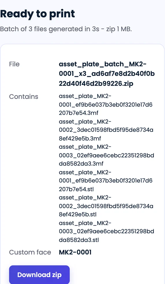
Every file comes out watertight, which matters more than it sounds: a mesh with holes will slice into something unpredictable around the engraving, and boolean operations on imported STLs are exactly where that tends to happen. Sixty parts are eight batches, seven of eight and one of four; start each batch at the number after the last one. The engraver’s serial numbers page covers the batch run itself, including 3MF and STL file sizes for a full plate.
Print one before you print sixty
Always run a single part first and look at the actual mark. You are checking three things: that the digits are separated, that the depth gives visible shadow on the real material colour, and that the recess did not land somewhere the slicer decided to bridge oddly. Five minutes here saves a whole plate.
Keep a record the number points to
A serial number is only useful if it resolves to something. Keep a plain spreadsheet with one row per unit: serial, print date, machine, filament batch, and where it went. This is the entire point of the exercise, and it is the step people skip.
When a part fails eighteen months later, the number on the underside turns “one of these broke” into “the ones from that spool, on that machine, in that week”. That is the difference between guessing and knowing.
Checklist
- Cut the mark in; never raise it.
- Pick a flat, non-mating, non-visible face with enough wall behind it.
- Depth 1.2 mm by default, at least five layer heights, and depth + 0.8 mm of wall.
- Cap height 4 mm or more on a 0.4 mm nozzle, so strokes reach 0.8 mm.
- Prefix plus zero-padded sequence, starting at 0001.
- Generate in batches, not one model at a time.
- Print one, inspect the mark, then commit the plate.
- Log every serial against machine, filament and destination.
About the author
Alok Kumar is a co-founder of 4Brains Technologies in Navi Mumbai.